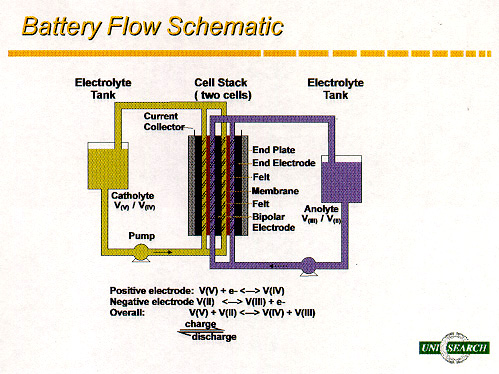
Figure 1 - Schematic diagram of the Vanadium Redox Battery System.
Abstract
In the development of self-sufficient power systems an energy gathering and conversion system can be linked to an energy storage facility. The Vanadium Redox Battery developed at the University of New South Wales is a high efficiency energy storage system that offers greater benefits over other energy storage systems for PV coupling. A 48 volt (nominal) 36 cell vanadium battery stack was constructed at UNSW to replace the 12 cell stack initially installed in the Solar Demonstration House in Thailand. A microprocessor controller built by the UNSW Centre for Photovoltaic Systems and Devices is being tested in conjunction with a 4 kVA GEEBUNG grid interactive inverter coupled to the 36 cell vanadium battery stack. Current indications are that the vanadium redox battery system can be successfully applied in residential photovoltaic applications to make energy self-sufficient housing a commercially successful and practical venture.
1. INTRODUCTION
In PV systems where the design involves coupling to batteries, lead-acid batteries have been favoured. Lead-acid batteries have certain constraints in the design of a PV system to be connected. For example, for long life, lead-acid batteries are commonly only used between 25 and 75 % of their state of charge (SOC). Thus only 50 % of the actual capacity is utilised and the battery cannot be left at low levels of charge for any extended period.
The Vanadium Redox Battery (VRB) was pioneered by workers at the Vanadium Battery Development Laboratory at the University of New South Wales and an initial patent was granted to Skyllas-Kazacos and Robins (1986). One of the VRB system's greatest assets is its high energy efficiencies ideally suited to load-levelling. The system can utilise 100 % of its capacity and be safely left fully discharged or at any SOC for any period.
In a PV lead-acid battery installation the PV installation requires extra PV which are only used when boost charging the battery. This extra charging is performed periodically to maintain cell equalisation however great amounts of hydrogen are liberated resulting in the loss of water and the need for a forced ventilated battery room. Maintenance of the lead-acid battery banks to check levels and the condition of individual cells is carried out at regular intervals. The lead-acid system needs adequate clearance between rows of batteries and also in tiered set-ups. The requirements of secondary battery installation and for installation and maintenance are covered by AS 3011.1 (1992b) and AS 2676.1 (1992a) respectively.
The VRB system is a redox battery system that can relax certain design parameters faced by PV system engineers as discussed by Largent et. al. (1993). In the VRB system illustrated in Figure 1, the energy is stored in the electrolyte. The power output is determined by the battery stack and the capacity by the volume of the electrolyte. The electrolytes are pumped from the electrolyte storage tanks through the respective half-cells in the stack and back. Since the same electrolyte is fed to all half-cells, boost charging is not required thus eliminating the need for extra PV. The battery system does not have to be overcharged and the problem in dealing with large amounts of hydrogen is eliminated.
With currently available materials, the life of the battery stacks is expected to be about 5-7 years, while the electrolyte has an indefinite life. The replacement cost therefore involves only replacing the battery stack which is essentially made up of recyclable material. In the lead-acid installation the entire battery bank needs replacing when the life expectancy is reached.
Figure 1 - Schematic diagram of the Vanadium Redox
Battery System.
There are other important factors that make the VRB system stand apart from other battery technologies. It is the only redox battery system that uses ions of the same metal in both half-cells. This eliminates capacity loss through electrolyte cross-contamination as experienced by the Fe/Cr redox battery. The SOC can be measured continuously therefore the capacity remaining in the battery can be read instantly. By the use of tapping cells in the battery, the battery can be charged at one voltage and discharged at another while also supporting an external load if needed.
A VRB system has been installed in a Solar Demonstration House in Thailand. A 4 kVA GEEBUNG grid interactive inverter is also installed along with a microprocessor controller built by the UNSW Centre for Photovoltaic Systems and Devices. The main focus of this paper is on the VRB system employed in this PV application. The benefits of using this system coupled to a PV installation is also discussed along with latest advances in VRB systems design.
2. VRB DESIGN APPLICATION
The VRB system components are continually undergoing advancement and battery simulation analysis is being employed to determine actual battery sizes and tapping arrangements.
2.1 VRB Simulation Design Package
In designing a battery system for a particular application it is of great benefit to know the expected performance of the battery system under different conditions. Restrictions may be placed on the design by the customer that can include parameters such as: the operating voltage range; the current limits to which the voltage range must comply and the SOC at which the maximum current must be available.
The simulation package takes into account the average cell resistance of the stack; the volume of electrolytes; maximum, average and minimum currents; as well as the determination of power output and capacity.
The initial 12 cell battery stack installed in the Solar Demonstration House was recently replaced by a 36 cell battery stack. The simulation program was used to obtain an operating comparison between the stacks utilising the same concentration and volume of electrolytes with the results presented in Table 1. It can be seen from the results in Table 1 that the operating voltage and peak power output of the 36 cell stack is higher than the 12 cell stack however the capacity is the same since it only depends on the concentration and volume of the vanadium electrolytes.
2.2 Cell Tapping
Voltage regulation may be controlled on the VRB battery stack by incorporating tapping cells. This is a design parameter that can be analysed using the VRB simulation package. A tapping cell is simply a cell in the battery stack that allows the input and output of current at a third terminal in addition to the 2 end electrodes. In use, the tapping cell becomes an end electrode for the desired external circuit, however an important factor is that this allows the battery to be simultaneously charged at one voltage and discharged at another voltage for the same current. The battery in effect can be used as an extremely efficient DC-DC transformer.
Average Cell Resistance - 2 Ohms.cm2
Electrolyte - 200L of 2M vanadium electrolyte per half-cell
SOC (%) Current (A)Charge 80 40 5
95             19.3           18.7          18.1

               50             17.5           16.8          16.3

               5              15.7           15.0          14.5

12 Cell     Discharge
               95             16.7           17.4          17.9

               50             14.9           15.6          16.1

               5              13.1           13.7          14.3
Peak Power (kW) @ 100A - 1.6 kW
Capacity (kWh) - 12 kWh
SOC (%) Current (A)Charge 80 40 5
95             57.9           56.0          54.3

               50             52.4           50.5          46.8

               5              47.0           45.1          43.4

36 Cell     Discharge
               95             50.2           52.1          53.8

               50             44.8           46.7          48.4

               5              39.3           41.2          42.9
Peak Power (kW) @ 100A - 5 kW
Capacity (kWh) - 12 kWh
3. VRB BATTERY STACK
The VRB stack is the power generator of the VRB system. The VRB system is an ongoing development with every component undergoing continuous analysis and improvement. The VRB stack employed in the Solar Demonstration House is of an external manifold design and employs electrodes which have a relatively high resistance compared with the new generation low resistance electrodes, more recently developed in the laboratory.
3.1 Flowframes
The latest VRB stack is of an internal manifold design and uses santoprene flowframe material to eliminate the need for gaskets and provides a leakproof battery stack that is robust and vibration tolerant.
The original flowframes were machined out of PVC which proved to be expensive and an inefficient means of production. The new santoprene flowframes are injection moulded ensuring high quality control and lower cost. Injection moulding is a very quick production method and is capable of commercial scale production. The cost involved is around 10% of the original flowframes which quickly offsets the initial capital cost of the mould. The precision gained using injection moulding raises the VRB stack production to a level that at present can be successfully supplied as a commercial grade component.
3.2 Electrodes
The electrodes employed in the VRB stack are composed of conducting plastic. The conducting plastic electrodes have felt bonded on the solution surfaces and become flowthrough electrodes. The electrodes must be inert; have a very low electrical resistance and be of sufficient mechanical strength to handle the pressure variances encountered during the operation of the VRB system (eg. up to 10 kPa pressure differentials can exist across an electrode or membrane component in the stack).
The electrodes have undergone much research and development, the main emphasis has been on developing a suitable conducting plastic sheet that meets all the above requirements while at the same time considering cost and a production method that can sustain large scale production. Polyethylene and polypropylene base electrodes have been successfully prepared and sheet extrusion has proved to be the best method of production. Costs as low as $1 per electrode sheet have been achieved.
Electrical resistivities as low as 0.5 Ohm.cm2 have been obtained for bipolar electrodes in combination with commercially available felt. End electrodes with felt on one side and a custom copper coating on the other side have yielded resistivities as low as 0.7 Ohm.cm2.
3.3 VRB Battery Performance
In load levelling applications high energy efficiencies are a primary concern. It is considered normal for a VRB battery system to achieve a level of 90 % energy efficiency at moderate current densities negating pumping losses. With the improved battery components and newly available membrane material this energy efficiency which is a characteristic of the VRB system can be achieved at considerably high power densities.
When pumping losses are calculated the higher the operating current density the smaller the pumping losses for a constant flowrate. The pumping losses at high operating current densities are in the range of 2-3% but increase as the operating current density in reduced. As this energy system is flexible however the pumps do not need to be operating continuously for the system to be on line. With this in mind the microprocessor controller developed by the UNSW Centre for Photovoltaic Devices and Systems controls the pump operations. The pumps are on continuously at high discharge and charging currents, intermittent at moderate levels and off at low levels. The pump on/off triggers are based on the battery voltage and current loads. This enables a maximum energy efficiency to be obtained at all levels of loading thus reducing the energy required for pumping in the operating system.
The VRB system can be charged and discharged simultaneously and illustrates the benefits of PV battery coupled power systems. The battery can be grid connected to also feed power back to the grid. Thus if 200 houses each fitted with a 5 kW system were simultaneously fed into the grid a 1 MW standby power net is available that can be simultaneously charged while supplying the power to the grid. This available energy also comes with an added bonus, it is truly a clean energy source that has the potential to alleviate the burden that extra conventional power generation would place on cities with an already high atmospheric pollution level.
4. CONCLUSION
The Vanadium Redox Battery system is a high efficiency energy storage system. It offers a degree of flexibility for PV battery coupled installations that has previously been unattainable. It also eliminates the need for extra PV since boost charging is not required. A 5kW/12kWh VRB system has been installed in the Solar Demonstration House in Thailand. Continual improvement of the VRB components continually lead to improved performance and efficiencies. It is therefore considered that this system has the potential to become linked to PV installations and offer cost effective, pure and clean energy self-sufficient housing.
5. ACKNOWLEDGEMENTS
The authors would like to acknowledge the assistance of Robert L. Largent from the Centre for Photovoltaic Devices and Systems, UNSW and Jim Wilson from the VRB Group.
The development of the vanadium redox battery has been funded by NERDDC, ERDC, NSW Office of Energy and Mount Resources. The authors are also grateful to Formica Australia P/L for donating the end plates used in the battery stacks.
6. REFERENCES
AS 2676.1, "Guide to the installation, maintenance, testing and replacement of secondary batteries in buildings, Vented cells", Standards Association of Australia (1992).
AS 3011.1, "Electrical installations - Secondary batteries installed in buildings, Vented cells", Standards Association of Australia (1992).
Largent R.L., Skyllas-Kazacos M. and Chieng J., "Improved PV System Performance Using Vanadium Batteries",Proceedings IEEE 23rd Photovoltaic Specialists Conference, Louisville, Kentucky, May (1993).
Skyllas-Kazacos M. and Robins R.G.,"The All Vanadium Redox
Battery", U.S. Patent No. 849 094 (1986).
Last modified 17th March, 1998